
MOUNTING A TAPERED BORE SPHERICAL ROLLER BEARING
Posted on Tuesday Apr 28, 2020 at 11:32PM in Mechanical

Mounting a Tapered Bore Spherical Roller Bearing on an Adapter Sleeve
Article By: Dan Whitehouse
Business Unit Manager
The install of a tapered bore spherical on an adapter sleeve can be a challenging task due to all the steps. The confusion comes when reading through the steps, checking the clearance gap before and during install and finally knowing how to read the manufacturer’s clearance chart. To the right are the listed steps for the install procedure so that we can clear up misunderstandings and confusion that goes with the bearing’s install. We recommend following the steps below and keeping the appropriate tools within arm’s reach to help streamline the install.
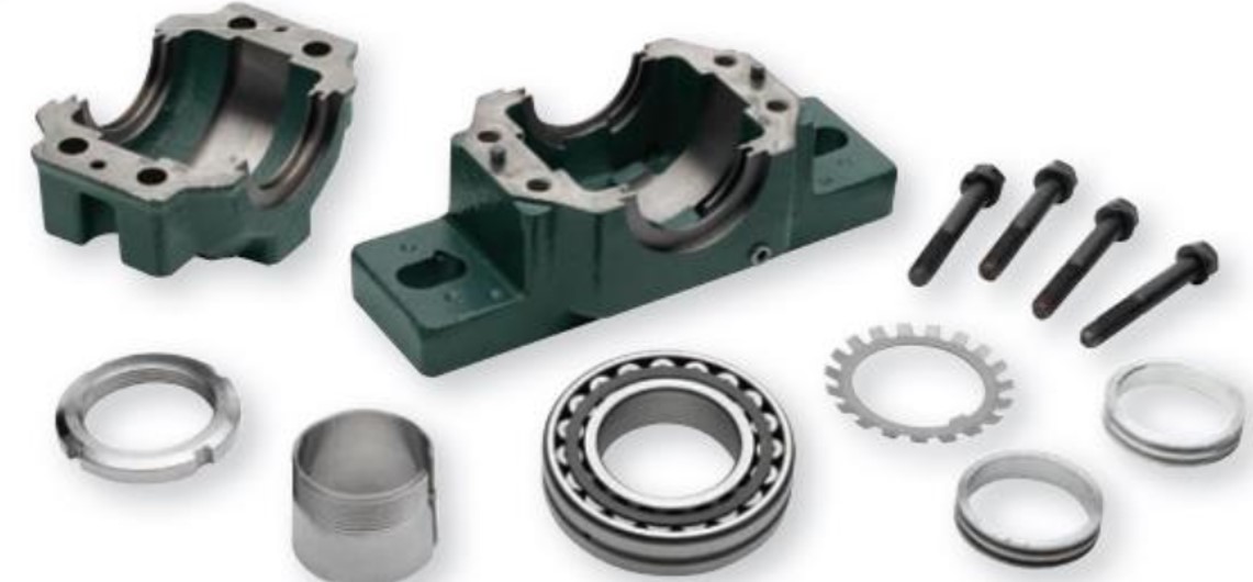
Image courtesy of ABB.
1.) Clean the shaft with an emery cloth or file to remove any rust or burrs from the shaft and then wipe the shaft down to remove the filings.
2.) Measure the shaft size to confirm that it is in spec based off the manufacturer’s suggestion for that sized bearing.
3.) Remove the adapter sleeve assembly from its packaging and disassemble.
4.) Position the adapter sleeve on the shaft in the approximate location of where the bearing will be operating when installed.
5.) Remove the bearing from its packaging and measure the unmounted radial internal clearance of the bearing to be certain that the bearing is in spec before install. Measure the clearance at the 12 o’clock position between the outer race and the top of the roller. When checking the gap in the bearing with the feeler blades, the blade should slide though the gap with some resistance; if the blade becomes pinched, pick a smaller sized blade and try again. When measuring with feeler blades use a sawing motion from the face of the roller to the middle of the bearing. When reading the clearance chart from the manufacturer make sure you are on the correct line for your bearing’s bore with the correct clearance columns. The nominal bearing bore column in the chart has two bore sizes listed. The left bore value is not included but everything over that bore is included up to and including the right bore value.
6.) After determining the bearing is in spec (write down your radial clearance you will need it later), place the bearing on the adapter sleeve and push the bearing up the adapter by hand until you cannot move it further, making sure the adapter has not moved on the shaft. Screw the locknut onto the threads of the adapter. Some people install the lockwasher at this point as well and some do not due to the fear of damage to it during the rest of the install.
7.) Refer to the manufacturer’s radial internal clearance chart for the correct reduction range (use your radial clearance before mounting value to determine the final mounted clearance). Using a spanner wrench or hammer and punch begin to tighten the locknut to reduce clearance in the bearing, while checking that the adapter hasn’t moved on the shaft. Be sure to check the reduction in clearance using feeler blades (the blade should slide though the gap with some resistance; if the blade becomes pinched, pick a smaller sized blade and try again) in-between rotations of the locknut to ensure that too much clearance is not taken out based off your mounted clearance value.
8.) If you didn’t install the lockwasher before, remove the locknut and install the lockwasher so that is sits flat against the bearing. Re-install the locknut until tight.
9.) Locate the lockwasher tang that is closest to the locknut slot. If slot doesn’t match up with a tang on the lockwasher, tighten the nut to match with the next closest lockwasher tang. Bend the tang into the locknut slot.
10.) Finally, ensure that the shaft and outer ring can be rotated
.