BEARING CURRENTS
Posted on Friday May 11, 2018 at 12:29PM in Mechanical
By: Blake Timmons
With the increased use of Variable Frequency Drives (VFDs) in industrial and commercial electric motors, there becomes a source of current flow through the bearing. Note that inverter-induced bearing currents and premature bearing failures occur in a relatively small percentage of installations and applications. Nevertheless, it's best to understand the topic when you run across the problem.
The damage to the outer or inner race of a motor bearing will look something like the pictures below.


The damage to the outer or inner race of a motor bearing will look something like the pictures below. In these photos. Notice that the “fluting” is seen as symmetrical damage which is a common sign of a bearing current issue. Also notice that damage can also occur that is not symmetrical, shown by individual random spots on metal surfaces. With motors using with an inverter, you need to be aware of the high-frequency current paths from the motor back to the inverter and to ground. This will help in understanding potential bearing current problems and remedies. High frequency motor bearing currents can occur in any motor driven by a drive using Pulse Width Modulation (PWM). This is a switching technique that switches high poser transistors to recreate the AC wave form to the desired frequency. The currents that are created are, induced into the motor bearing creating a current path and can damage the motor bearings if they reach a sufficient magnitude. Note that the, motor bearing damage typically doesn’t occur rapidly.To help in our understanding of this issue, realize that High Frequency motor bearing currents can be generated in three different manners. These can be present individually or in combination.
The first mode is the Circulating type.
This type normally only occurs in larger motors greater than 100 Hp. Essentially non-symmetrical or uneven currents in the motor’s magnetic paths cause a magnetic coupling to occur that induces a high frequency voltage into the rotor along its axial length. If sufficiently high, this induced voltage causes a current to flow in the circular path created by the rotor shaft, the two bearings, and the frame of the motor.
The second mode is from Capacitive Coupling.
This type occurs in all motor sizes but is normally only a problem in smaller motors. Current is coupled from the stator windings to the rotor. This tends to raise the voltage of the rotor above that of the stator frame. If the voltage reaches a sufficient level, one of more of the motor bearings will experience a voltage breakdown and discharge back to the stator frame. This discharge current tends to damage the motor bearings – most noticeably the inner race.
The last mode is from the Frame Voltage or Shaft Grounding.
This type of bearing current can occur in any size motor; however, it is limited to those cases where the motor’s physical load provides an electrical grounding path. Current is coupled from the stator windings to the stator frame, and tends to raise the voltage of the frame above that of the drive’s equipment ground. This type of high frequency bearing current can also damage mechanical load bearings such as gearbox or pump bearings.
A Grounding Brush from Helwig Carbon can be used to reduce the shaft voltages.
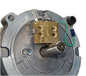
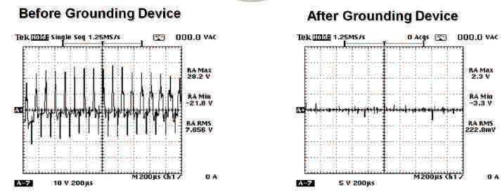
Shown below is a recommended shaft grounding device. As can be seen by the two oscilloscope traces, the shaft grounding device dramatically reduces rotor
shaft voltage to a safe level that avoids dangerous bearing currents.